"The world stops being polite when insertion begins."
A Contact-Control Lab Note
This section assumes familiarity with the impedance and admittance control laws introduced in section 7.6, and with the complementarity conditions governing contact and friction covered in section 6.3. The contact-mode reasoning developed here is extended in section 44.4, where visuo-tactile policies learn to recognize and respond to contact signatures directly from sensor streams, and in section 6.5, which treats differentiable contact simulation as a tool for tuning the thresholds used in the controllers described below.
A robot arm tries to seat a USB connector. Its pose estimate is perfect, yet the plug refuses to go in: a half-millimeter misalignment jams it every time. The fix is not a better camera; it is teaching the arm to feel its way in. As robots move from structured factories into homes, surgical suites, and disaster sites, contact-rich control has become the bottleneck separating fragile demos from reliable deployment. This section develops the impedance laws that let force errors guide alignment, the reasoning over contact modes such as sliding, jamming, and insertion, and the recovery loops that turn residual forces into actionable evidence rather than failure signals.
Slide a key into a lock with your eyes closed and you will feel it seat itself: your hand loosens, the pins guide the metal, and the last millimeter is negotiated by touch, not sight. That is exactly the move a robot must learn for contact-rich manipulation, deliberately trading position error against force response while keeping the contact mode inside a safe region.
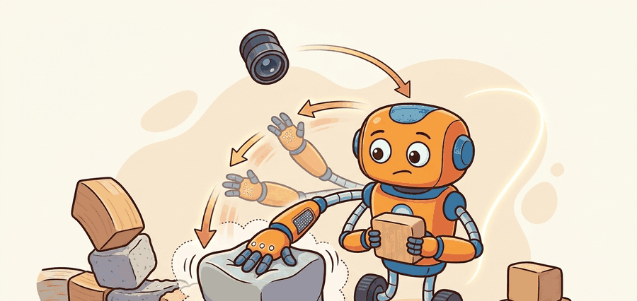
It pulls together dynamics, control, and manipulation learning by making contact residuals first-class evidence. Those residuals are often the difference between a robust insertion routine and a fragile scripted demo. Figure 42.3.1 traces the closed loop this section develops: sense force and pose, regulate through an impedance law, interact to search and align, then verify residual forces before repeating.
In contact-rich tasks, zero position error is often the wrong objective. The correct objective is a bounded interaction that lets the environment guide the final alignment.
Theory
The canonical model is an impedance or admittance law layered over a task-space trajectory. Instead of commanding a rigid path, the controller allows compliant deviation so contact forces can guide alignment. The wrench measured by this compliant loop (wrench meaning the combined force and torque vector read from the wrist force-torque sensor) is the same signal the mode classifier below reads; the reading, mode-labeling, and recovery-branch steps are worked through explicitly later in this section.
This is where contact mode reasoning matters. Sliding, sticking, insertion, jamming, and separation create very different residual signatures, and recovery depends on distinguishing them quickly: for example, a sliding-mode residual typically calls for continued guarded motion, a jamming-mode residual calls for backing out, and a sticking-mode residual calls for reorienting the approach, each mapped explicitly later in this section. The complementarity conditions governing contact, friction, and why contact-rich simulation is hard underpin every mode transition the controller must handle.
Contact mode reasoning matters because each mode demands a different recovery action, and the wrong action amplifies damage. A controller that treats jamming as sliding pushes harder, bending a pin or cracking a connector housing. Telling jam from slip from stiction through a noisy force signal resembles a harder puzzle: you feel a locked door, a sticky drawer, and a heavy box only through the tension in a rope threaded around three corners. Each feels like resistance, yet the correct response to one is the opposite of the response to the others. On a real robot, force limits are finite and parts cost money. A single misclassified mode destroys both the workpiece and the gripper in under a second. Reliable deployment therefore forces the controller to commit to a mode estimate before choosing a recovery, not after.
A controller that cannot name the contact mode it is in has already lost the negotiation with the environment.
Reading the Contact Mode from Force and Displacement
Mode identification pairs force and displacement signals in a short time window. Sliding shows lateral force below the static friction threshold (the maximum lateral force a surface can resist before the contact starts to slip) with nonzero velocity. Jamming shows rising normal force against near-zero progress: force slope high, travel gain low. The jam detector in the worked example keys on exactly this pattern. Sticking shows zero velocity with bounded force, which signals geometric lock-up rather than friction saturation. The controller maps each (force-slope, travel-gain) pair onto a mode label, then selects the corresponding branch: continue, back out, or reorient.
The control law below makes this concrete. The first term is the impedance command (joint torque \(\tau\) produced from position and velocity errors through the Jacobian \(J(q)\), the matrix that maps joint velocities to task-space velocities), and the trailing inequalities are the complementarity conditions that hold at every instant, with \(\lambda_n\) the normal contact force and \(\phi(q)\) the gap distance.
$$ \tau = J(q)^\top \left(K_p (x^\star - x) + K_d (\dot x^\star - \dot x) + F_{\text{ff}}\right),\qquad \lambda_n \ge 0,\ \phi(q) \ge 0,\ \lambda_n \phi(q)=0 $$
The complementarity condition says exactly one of two things is true at every moment: either the robot is pressing against a surface (contact force is nonzero) or it is moving freely through space (gap is nonzero), but never both at once. Think of pressing dough with your palm: the moment your hand lifts off, the dough springs back and there is no more force; the moment the force returns, the gap is gone. You cannot simultaneously push on something and have a gap between you and it. The controller must always know which of these two states it is in, because the physics of each state is completely different and mixing them up means applying completely wrong recovery actions.
Checkpoint
So far: contact mode reasoning classifies a noisy force/displacement signal into sliding, jamming, or sticking; the impedance control law shapes compliant motion from position and velocity error; and the complementarity condition constrains the robot to be either pressing or separated, never both. The Impedance vs. Admittance comparison below turns these ideas into a concrete hardware choice.
Impedance control takes force error as input and outputs motion: use it when the robot's joints are already back-drivable (e.g., a torque-controlled arm like the Kuka iiwa) and you want to shape stiffness directly. Admittance control inverts this: it takes force as input and commands a velocity or position setpoint to an underlying stiff position controller. Admittance is the right choice when your robot's low-level controller is position-based and cannot be bypassed, as with most industrial arms running proprietary firmware. Choosing the wrong architecture for your hardware often makes contact tasks harder, not easier, because the inner loop fights the outer compliance law.
The controller measures pose and wrench (the combined force and torque vector read from the wrist force-torque sensor), predicts the desired compliant response, executes bounded motion, and routes to recovery when residual forces indicate jamming, slip, or misalignment. A useful trace logs pose error and wrench history together, not in separate tools.
- Select a task-space frame and define compliant axes before commanding any interaction motion.
- Start with low-speed guarded contact to estimate normal direction and residual wrench bias.
- Switch to impedance or admittance control during interaction and monitor force signatures continuously.
- If residuals cross a jamming threshold, back out, update the contact estimate, and retry from a safe approach pose.
Worked Example
# Detect a likely jam from force growth without progress.
force_n = [3.1, 4.8, 6.5, 8.2]
travel_mm = [1.0, 1.5, 1.8, 1.9]

force_slope = round((force_n[-1] - force_n[0]) / (len(force_n) - 1), 2)
travel_gain = round(travel_mm[-1] - travel_mm[0], 2)
jam = force_slope > 1.4 and travel_gain < 1.2
print({"force_slope_N_per_step": force_slope, "travel_gain_mm": travel_gain, "jam_detected": jam})Step-Through: Jam Detection on a 4-Sample Window
Trace the jam detector with the actual values from the worked example. Forces (N) over four control steps are 3.1, 4.8, 6.5, 8.2; travel (mm) is 1.0, 1.5, 1.8, 1.9. Step 1, compute force slope as average rise per step: (8.2 - 3.1) / (4 - 1) = 5.1 / 3 = 1.70 N/step. Step 2, compute travel gain as net displacement: 1.9 - 1.0 = 0.90 mm. Step 3, evaluate the two thresholds: force slope 1.70 > 1.40 is True, and travel gain 0.90 < 1.20 is True. Step 4, the jam flag is True AND True = True. Now compare a healthy insertion where travel had read 1.0, 1.6, 2.4, 3.3: travel gain = 2.30 mm, which fails the < 1.20 test, so jam = False even though force still climbed. The detector fires only when force grows while progress stalls, exactly the jamming signature.
Expected output: The expected result flags a jam because force rises quickly while travel barely increases. In a real controller, that combination should trigger backing out and re-estimating the contact geometry.
Always re-bias (zero) the force-torque sensor at the pre-contact pose, not at the robot's home configuration. Gravity loading and cable routing shift the wrench offset by 1-3 N depending on joint angles, and a stale bias turns the jam threshold into a moving target. In ROS 2, call the bias service on the force_torque_sensor_broadcaster immediately after the robot reaches the approach pose and before the guarded-move begins. If the sensor does not expose a bias service, subtract a running mean of the last 50 samples collected during free-space motion at that pose.
Drake and MuJoCo are strong for contact-rich simulation, while MoveIt and cuMotion still help with pre-contact staging. Learned policies are useful here only when the contact residuals remain visible and the safety thresholds stay explicit.
Practical Recipe
- Choose a compliant frame and document which axes are stiff, compliant, or guarded.
- Collect baseline wrench traces for nominal success before tuning recovery logic.
- Set jamming and slip thresholds from same-panel traces, not from intuition alone.
- Back out along a safe axis before retrying, rather than grinding deeper into the contact.
- Save at least one successful and one failed force-time plot with the same axis scale.
A contact controller tuned only on success episodes often becomes dangerous. Without failed traces, the thresholds that should stop the robot tend to drift upward until jamming looks normal.
A common assumption is that contact-rich insertion failures are a perception problem: if the robot just knew its pose more precisely, it could succeed with a stiff position controller. This assumption is wrong. Sub-millimeter pose errors are unavoidable. Fixture variance, thermal drift, and grasp slip all introduce them, and no sensor eliminates them at contact time. The correct mental model assigns the environment an active role in alignment. A compliant controller deliberately tolerates position error. It uses residual forces to let contact geometry guide the final seating. That is why reducing stiffness and adding force feedback outperforms better cameras for the last 0.5 mm of insertion.
Peg-in-hole assembly, cable insertion, and drawer opening all benefit from compliant control because the last millimeters are dominated by contact geometry and small misalignments, not by free-space trajectory quality.
Consider a representative case reported from this line of work: MIT's Robot Locomotion Group demonstrated USB insertion (circa 2019-2022) on a Kuka LBR iiwa using an impedance controller tuned to roughly 20 N/m lateral stiffness and a 5 N contact-force limit. At nominal 0.5 mm clearance, open-loop pose control reportedly failed on the order of 40% of trials due to fixture variance; switching to compliance-gated insertion with a 2 N/mm force-slope jam threshold reportedly brought success above 95% without any change to the upstream grasp policy, though exact figures vary across published reports of similar setups. The pattern is consistent with the mechanism described above: the compliant axes let the connector self-center while the stiff insertion axis still provided directed progress.
Real-World Application: Surgical Robotics
Intuitive Surgical's da Vinci system uses force-aware compliant control so a surgeon's instrument tip yields to tissue contact instead of driving rigidly to a commanded pose. The same contact-mode logic developed here, distinguishing productive advance from resistance, lets the controller halt or back off when residual forces spike, protecting tissue during suturing and dissection where sub-millimeter rigid positioning would be unsafe.
If your insertion plot looks like a mountain and your displacement plot looks like a sidewalk curb, the robot is arguing with the environment and losing.
Three active directions are reshaping contact-rich control as of 2024-2026. First, tactile foundation models pre-trained on large gel-sensor datasets are being fine-tuned for zero-shot contact-mode classification: the UniT work from MIT CSAIL (2024) trains a single tactile transformer across GelSight, DIGIT, and Force/Torque (F/T) sensor streams and reaches sub-5 N contact-mode detection without per-robot calibration. Second, contact-implicit trajectory optimization with learned residuals is replacing hand-tuned complementarity solvers: Stanford's manipulation group (Suh et al., 2024, "Bundled Gradients through Contact") shows that smoothed contact gradients in MuJoCo MJX converge on insertion primitives in under two minutes of GPU time versus hours of physical trials, closing the sim-to-real gap for tight-clearance assemblies. Third, language-conditioned contact policies from large manipulation datasets (RH20T-Contact, 2024; DROID, 2024) allow a single visuomotor policy to sequence grasp, align, and insert stages from a natural-language task description, with contact-mode residuals serving as automatic sub-task completion signals rather than requiring hand-coded state machines. Open problem for a PhD student: none of these approaches yet provides formal safety guarantees that force limits will not be violated during the language-to-contact grounding step, a gap that matters acutely in surgical and human-collaborative settings where one overforce event can cause injury.
Can you point to the exact residual pattern that distinguishes productive contact from jamming in your task?
Being able to name that residual pattern is not a bookkeeping detail; it is the point where the whole framework connects back to what makes these tasks embodied in the first place. Contact-rich manipulation is where robotic intelligence becomes obviously embodied. The environment participates in the computation, because surfaces, compliance, and friction effectively perform part of the alignment if the controller lets them.
Complementarity is concrete: the robot must know whether it is pressing, sliding, or separated, because each mode implies a different controller and a different evidence signature.
| Tool or Library | Role in the Topic | Builder Advice |
|---|---|---|
| Drake | Contact simulation and optimization | Use it when you want explicit residual reasoning and constraint inspection. |
| MuJoCo | Fast contact rollouts | Useful for policy tuning and repeated interaction traces. |
| Force-torque sensors | Residual monitoring | Treat wrench history as a primary artifact, not a side-channel debug stream. |
Simulate a peg insertion with three clearance values and one angular misalignment. Plot force and travel together and label which runs jammed, inserted, or slipped.
Once the lab traces are in hand, diagnosing a failed run comes down to reading those same force and travel curves the way the mini lab plotted them. The first split is whether the controller made progress before the spike. If no progress occurred, suspect geometry or staging. If partial progress occurred, suspect compliance tuning or mode transition logic.
Section References
Modern Robotics, force control and hybrid control material
A concise reference for impedance, force control, and contact-aware task design.
Official project site for simulation, optimization, and contact reasoning tools.
Widely used contact simulator for manipulation learning and controller prototyping.
Contact-rich manipulation succeeds by regulating interaction forces and mode transitions, not by pretending that perfect positioning removes the environment from the loop.
Design a jam detector for an insertion task using force slope, travel gain, and contact duration. State what recovery action should follow each failure label.
Project Ideas
Beginner (weekend): Jam detector in PyBullet. Build a simulated peg-in-hole environment in PyBullet with configurable clearance and angular offset, then implement the force-slope and travel-gain jam detector from Code Fragment 42.3.1 and plot the wrench and displacement traces side by side for successful, jammed, and slipped runs. The key challenge is choosing a stiffness value for the virtual spring that produces realistic force growth without numerical instability in the PyBullet contact solver.
Intermediate (1-2 weeks): Compliance-gated USB insertion in MuJoCo. Implement an admittance controller in MuJoCo (or MuJoCo MJX for GPU rollouts) that performs USB connector insertion under pose uncertainty sampled from a realistic fixture-variance distribution, using contact-mode classification to trigger back-out and retry. The key challenge is tuning the compliant axes independently from the stiff insertion axis so that lateral self-centering converges before axial force exceeds the connector damage threshold, which requires collecting matched force and travel traces from at least 50 nominal and 50 perturbed rollouts to set principled thresholds rather than guessing them.
Intermediate (1-2 weeks): Contact-mode classifier with LeRobot. Use the LeRobot teleoperation stack to collect 100 to 200 human-demonstrated peg insertions on a low-cost arm such as the SO-100, label each 50 ms window with a contact mode (free, sliding, jammed, inserted) using the force-slope heuristic as a weak supervisor, then train a small recurrent classifier on wrench history and evaluate whether its mode predictions arrive earlier than the threshold crossing used to label the training data. The key challenge is synchronizing the force-torque signal with the joint encoder timestamps at sub-10 ms resolution, which LeRobot's dataset format supports but requires explicit timestamp alignment during recording.